| Basic construction |
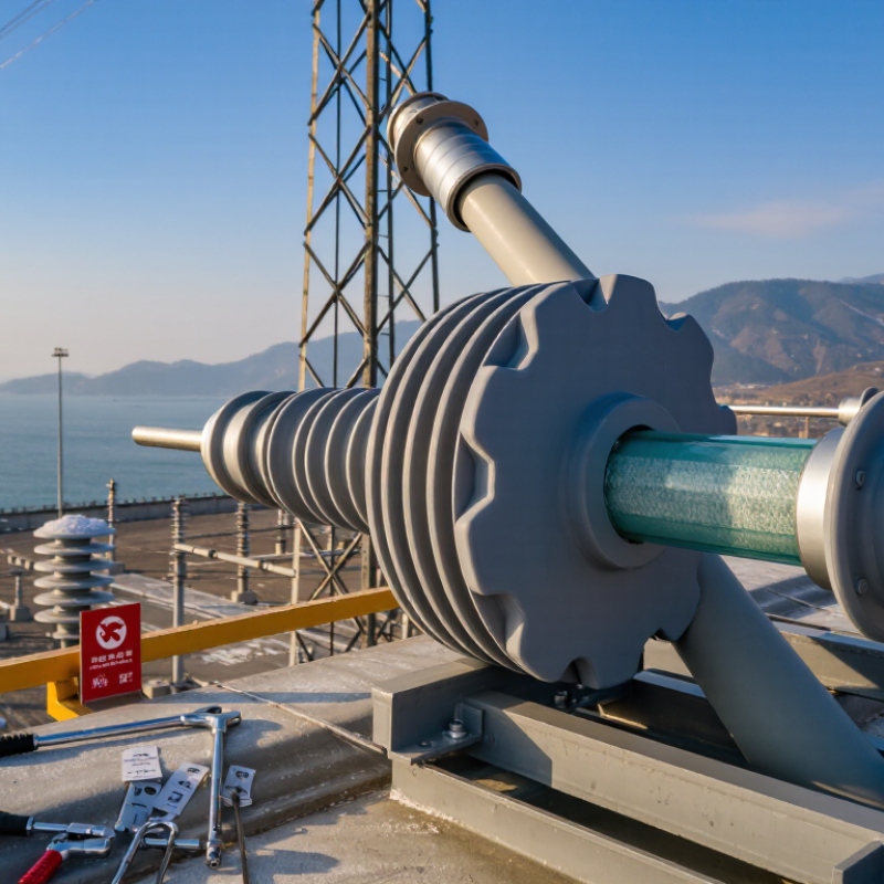
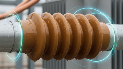
Silicone rubber weather sheds bonded to a fiberglass-reinforced polymer rod with metal end fittings. |
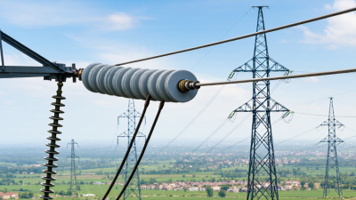
EPDM weather sheds combined with a fiberglass-reinforced polymer rod and metal end fittings. |
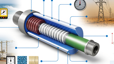
Glazed ceramic disc with cemented metal hardware. |
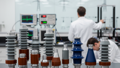
Toughened glass disc with cemented metal hardware. |
Composite designs are generally preferred where low mass, contamination performance, and reduced handling effort are important. |
| Typical system-voltage application |
11 kV to 550 kV and above, depending on insulation length and assembly design. |
11 kV to 220 kV and above, depending on formulation, housing design, and qualification testing. |
11 kV to 1,000 kV class systems using appropriate disc strings. |
11 kV to 1,000 kV class systems using appropriate disc strings. |
Do not select by system voltage alone; insulation coordination and required creepage distance are decisive. |
| Rated voltage and insulation coordination |
Specified by the complete insulator assembly; common design checks include power-frequency withstand and lightning impulse withstand. |
Specified by the complete insulator assembly; electrical performance depends on shed profile, spacing, and material formulation. |
Specified by the number and type of discs in the string; individual disc values are commonly standardized. |
Specified by the number and type of discs in the string; individual disc values are commonly standardized. |
Match the assembly to IEC 60071 insulation-coordination requirements and the utility's switching-impulse criteria. |
| Typical creepage-distance design |
Approximately 16 to 43 mm/kV of highest system voltage, selected according to pollution severity and site conditions. |
Approximately 16 to 43 mm/kV, with profile and material verified for the intended pollution environment. |
Approximately 16 to 43 mm/kV using disc-string configuration and pollution-class selection. |
Approximately 16 to 43 mm/kV using disc-string configuration and pollution-class selection. |
Use the applicable pollution classification and corrected creepage method; higher values may be required for severe contamination or salt exposure. |
| Housing material properties |
Hydrophobic silicone surface; typically maintains water-repellent behavior after contamination and light surface transfer. |
Good elastomeric flexibility and electrical insulation; hydrophobicity recovery is generally less pronounced than with silicone rubber. |
Hard, glazed ceramic surface; non-hydrophobic and more dependent on profile, washing, and creepage distance. |
Hard glass surface; non-hydrophobic and more dependent on profile, washing, and creepage distance. |
Silicone rubber is normally the strongest choice for wet, salt-laden, or heavily polluted service when properly qualified. |
| Resistance to tracking and erosion |
Typically very good when compliant with the tracking-and-erosion requirements of IEC 61109 and IEC 62217. |
Good when correctly formulated and tested; long-term resistance is formulation- and profile-dependent. |
Very good inorganic surface resistance; glaze damage can reduce service performance. |
Very good inorganic surface resistance; surface fracture or puncture requires replacement. |
Request type-test evidence for tracking, erosion, corona, and accelerated aging rather than relying only on material descriptions. |
| UV and weathering performance |
Very good with suitable high-temperature-vulcanized silicone and UV-stabilized formulation. |
Good to very good, depending on polymer formulation, stabilizers, and exposure conditions. |
Very good against UV exposure; glaze and cement interfaces still require inspection. |
Very good against UV exposure; mechanical damage may be visible or may require closer inspection. |
For high-UV locations, require artificial-weathering and field-exposure evidence for the exact housing compound. |
| Typical continuous operating temperature |
Approximately −50 °C to +50 °C for many utility designs; verify the specified compound and fitting limits. |
Approximately −40 °C to +50 °C for many utility designs; verify low-temperature flexibility and aging data. |
Approximately −50 °C to +55 °C, subject to glaze, cement, and hardware design. |
Approximately −50 °C to +55 °C, subject to glass type, cement, and hardware design. |
Use the manufacturer's declared temperature range for the complete assembly, not the polymer or ceramic alone. |
| Typical rated mechanical load range |
Approximately 40 to 300 kN for suspension and tension designs; higher values are available in specialized assemblies. |
Approximately 40 to 300 kN for comparable suspension and tension designs, subject to rod and fitting design. |
Approximately 40 to 420 kN for standardized disc and string arrangements. |
Approximately 40 to 420 kN for standardized disc and string arrangements. |
Compare the specified mechanical failing load, not only the nominal voltage or physical size. |
| Mechanical load categories |
Tensile, bending, torsional, and cantilever loads may apply depending on the fitting arrangement. |
Tensile, bending, torsional, and cantilever loads may apply depending on the fitting arrangement. |
Primarily tensile loading in suspension strings; bending and impact resistance depend on the assembly. |
Primarily tensile loading in suspension strings; impact damage can be a significant consideration. |
For line-post or compact structures, verify cantilever and combined-load ratings in addition to tensile strength. |
| Mechanical failing-load tolerance |
Commonly specified with a safety margin above the routine service load; exact design value is product-specific. |
Commonly specified with a safety margin above the routine service load; exact design value is product-specific. |
Standardized mechanical ratings are available, but cement, pin, and cap condition strongly influence actual performance. |
Standardized mechanical ratings are available, but hidden impact damage can reduce residual strength. |
Require routine mechanical tests and type-test results for the exact design and hardware combination. |
| Weight compared with conventional disc strings |
Typically about 50% to 80% lighter than an equivalent porcelain string, depending on voltage and rating. |
Typically about 50% to 80% lighter than an equivalent porcelain string, depending on design. |
Higher mass; installation and tower loading increase as the number and size of discs increase. |
Generally lighter than porcelain, but still heavier than most composite designs for equivalent line duties. |
Composite construction can reduce transport, tower, and installation loads. |
| Resistance to impact and vandalism |
Good resistance to handling impact; the polymer housing can conceal internal rod or interface damage. |
Good resistance to handling impact; damage assessment may require electrical or mechanical inspection. |
Susceptible to brittle fracture from impact, shooting, or improper handling. |
Can shatter or puncture after impact; damaged units may require immediate replacement. |
For vandalism-prone routes, compare anti-vandal features, inspection methods, and spare-unit logistics. |
| Water absorption and sealing |
Housing is normally non-porous; sealing at the rod and end-fitting interfaces is critical. |
Housing is normally non-porous; interface sealing and long-term adhesion must be verified. |
Ceramic body has low water absorption when properly glazed; cement interfaces require protection. |
Glass body has very low water absorption; metal-glass and cement interfaces require inspection. |
For composites, check sheath-to-core bonding, end-fitting sealing, and protection against moisture ingress. |
| Inspection and maintenance |
Visual inspection, infrared inspection, leakage-current monitoring, and targeted diagnostic testing may be used. |
Visual inspection and targeted electrical diagnostics are recommended; surface aging should be monitored. |
Visual inspection can identify chips, cracks, glaze damage, and cement deterioration. |
Visual inspection can identify puncture, shell damage, and fragments; hidden damage may require additional assessment. |
Choose an inspection method compatible with the utility's maintenance capability and access conditions. |
| Applicable reference standards |
IEC 61109, IEC 62217, IEC 60071, and applicable project or utility specifications. |
IEC 61109, IEC 62217, IEC 60071, and applicable project or utility specifications. |
IEC 60383-1, IEC 60120, IEC 60433, IEC 60071, and applicable project specifications. |
IEC 60383-1, IEC 60120, IEC 60433, IEC 60071, and applicable project specifications. |
Confirm the current edition of each standard and whether regional standards or utility-specific tests also apply. |
| Best-fit application profile |
Coastal corridors, industrial pollution, compact towers, high wind, retrofit projects, and locations requiring reduced weight. |
Moderate pollution environments and applications where elastomeric flexibility is useful and qualification data is available. |
Long-established systems, high mechanical ratings, and projects with established porcelain inspection and replacement practices. |
Transmission lines requiring standardized disc strings, visible damage indication, and established glass-insulator maintenance procedures. |
Select the material only after comparing electrical, mechanical, environmental, installation, and lifecycle requirements together. |
| Primary limitations |
Potential for interface aging, rod corrosion, housing damage, and concealed internal defects if design or sealing is poor. |
Lower hydrophobicity recovery than silicone in many formulations and greater dependence on compound quality and aging control. |
High weight, brittle damage, possible cement aging, and greater sensitivity to impact and handling. |
Impact-related breakage, possible puncture, and the need for replacement after significant mechanical damage. |
Use factory qualification, traceability, incoming inspection, and a defined field-maintenance plan to control risk. |
|
Reference framework: IEC 61109 for composite suspension and tension insulators for AC overhead lines; IEC 62217 for polymeric high-voltage insulators; IEC 60071 for insulation coordination; IEC 60383 for ceramic or glass insulator units. Values shown are typical comparison ranges, not guaranteed product ratings.
|