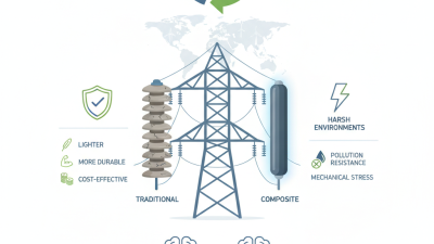
How to Choose the Right Composite Isolator
Choosing the right Composite Isolator starts with the conditions it must withstand. A unit beside a coastal substation faces salt, wind, and moisture. One on an inland line may face dust, temperature swings, or heavy pollution. These details matter. So does the system voltage, mechanical load, mounting arrangement, and required creepage distance. A catalogue match is not enough.
As an illustrative expert voice—not a verified quotation—composite-insulator materials engineer Dr. Mira Chen puts the principle this way: “Choose for the site, not just the specification sheet.” That is a useful reminder, though no single rule replaces engineering review. Compare housing material, core strength, end-fitting design, manufacturing quality, and documented test performance. Ask how the product has performed in service under similar conditions. Check that the supplier’s ratings and test reports match the intended application.
There are trade-offs. A lighter insulator can ease handling, but installation details still matter. A higher creepage distance may help in polluted environments, yet it does not fix poor maintenance or unsuitable design. Small oversights can become expensive. This guide explains the key selection factors and the questions worth asking before purchase. It also notes where available information may be incomplete. Verify every critical rating with the manufacturer and a qualified power-system engineer before making a final choice.
Define the Application Voltage and Pollution Class Using IEC 60815 (16–31 mm/kV)
How to Choose the Right Composite Isolator
Define the Application Voltage and Pollution Class Using IEC 60815 (16–31 mm/kV)
Start with the system’s highest voltage for equipment, not just its nominal operating voltage. Then assess the installation site under IEC 60815. Consider salt spray, industrial dust, agricultural deposits, and how often natural rain washes the insulator. A coastal substation may face different contamination from a dry inland line. Small site details matter.
Use the 16–31 mm/kV range as a selection guide, not a universal rule. Identify the site pollution severity and corresponding reference unified specific creepage distance in the applicable IEC method. Confirm the voltage basis and apply relevant corrections for insulator profile, diameter, and site conditions. The right value depends on the actual exposure. A neat calculation can still miss seasonal deposits or sheltered surfaces.
Tips: Photograph nearby insulators after dry weather and after rain. Compare contamination patterns with maintenance records, where available. If site data is thin, state your assumptions and seek a qualified review; guessing the pollution class is not a robust design method.
Set Creepage Distance and Insulation Level for the Site Conditions
Choose creepage distance from the pollution the isolator will actually face, not a regional label alone. Salt spray, cement dust, and long dry spells can create conductive surface deposits. IEC TS 60815-1 lists reference unified specific creepage distances of 22, 27.8, 34.7, 43.3, and 53.7 mm/kV across pollution classes from light to very heavy. These values help screen designs; they do not replace a site assessment. Salt changes everything. Check nearby coastlines, industrial emissions, prevailing winds, and whether rain reliably washes the insulator. It often does not.
Then coordinate the insulation level with the system’s highest voltage and expected switching and lightning surges. IEC 60071-1 provides the framework for selecting withstand levels, while altitude and installation geometry can affect the final choice. A practical review should compare the specified impulse withstand voltage with the network study, then confirm clearances against the actual mounting arrangement. Look closely at the yard. A dusty crossarm or sheltered underside may stay dirty after rain. Field records and maintenance observations are valuable, though one inspection can miss seasonal conditions. Recheck assumptions with local measurements where possible, especially after dry, windy periods or salt fog.
Choose Rated Failing Load (kN) for the Line’s Mechanical Loads
Rated failing load, often listed as specified mechanical load (SML), must exceed the insulator’s calculated mechanical demand. Include conductor tension, wind, ice, line angles, and uneven spans. A straight-line suspension string and an angle structure do not carry the same loads. Check the actual load path.
For example, if a project calculation gives a 42 kN peak tensile demand, a project-defined 1.5 design factor would require at least 63 kN SML. That factor is illustrative, not universal; use the applicable design criteria and load combinations. IEC 60826:2017 provides reliability-based design criteria for overhead lines. IEC 61109:2010 specifies routine tensile testing at 50% of an insulator’s SML, a useful production-quality check, not a substitute for design margin. Review the test certificate and confirm the rating applies to the complete insulator assembly, including fittings. Small details matter. Corrosion, eccentric loading, or a poor connection can undermine a sound rating. I would also revisit the assumed peak load: field conditions rarely match a neat calculation exactly.
How to Choose the Right Composite Isolator: Choose Rated Failing Load (kN) for the Line’s Mechanical Loads
Compare the estimated peak mechanical load per insulator with an example rated failing load selection.
How to use this chart: The load values and ratings are illustrative examples, not prescribed selections or standard rating classes. Choose a rated failing load that meets the applicable design requirements for the maximum mechanical load, including required safety margins and relevant service conditions. Confirm the final selection against the project specification and applicable standards.
Assess Silicone Housing and Fiberglass Core Against IEC 62217
How to Choose the Right Composite Isolator
Assess Silicone Housing and Fiberglass Core Against IEC 62217
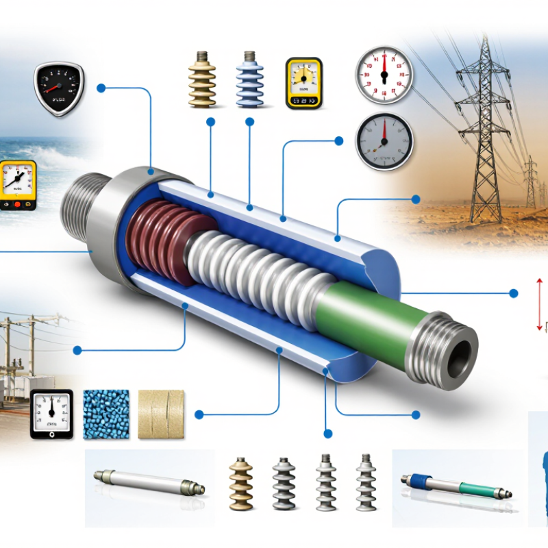
A composite isolator depends on two parts working together: the silicone housing and the fiberglass-reinforced polymer core. The housing sheds water and helps resist pollution, tracking, and erosion. The core carries the mechanical load. IEC 62217 provides common design and testing requirements for polymeric insulators, but it does not make every product interchangeable. Check that the test report matches the proposed design, including its housing, core, and end fittings.
Look closely at the silicone surface and the interfaces near the metal fittings. Ask how the design was evaluated for tracking, erosion, and water diffusion, and request reports that identify the tested specimen. For the fiberglass core, review mechanical ratings and how moisture is kept from entering through seals or exposed interfaces. These details matter in service. A polished data sheet can still leave questions unanswered.
Tips: Compare the stated operating conditions with your site’s pollution, rainfall, and mechanical loads. Confirm the applicable IEC 62217 edition and any product-specific requirements with a qualified engineer. A test report is useful, not magic. Also consider installation quality and inspection access; these can be overlooked during selection.
Verify Type and Routine Tests Under IEC 61109 Before Installation
How to Choose the Right Composite Isolator
Before installation, confirm the isolator’s type matches the application and the requirements of IEC 61109. The standard covers composite suspension and tension insulators for overhead lines. Check the rated voltage, mechanical load rating, end-fitting arrangement, and creepage distance against the project specification. A product that looks right on a drawing may not suit the site’s pollution level or exposure conditions. Details matter.
Review type-test evidence for the relevant design and configuration, not merely a similar-looking product. Then confirm routine-test records for the supplied units, including clear identification and traceability to the production batch. Ask which edition of IEC 61109 was applied and whether any deviations are documented. A certificate alone may not answer every question; reports should identify the tested design and results. I would pause if those details are vague.
Tips: Match the test documents to the exact model and order. Check labels before installation, and keep records with the asset file. Small discrepancies are easy to overlook. A second review can catch them.